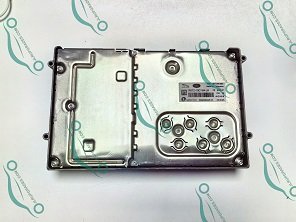


Technical Specifications and Functionality
The RK75-19C164-JA amplifier operates as a node on the MOST150 (Media Oriented Systems Transport) bus network. Key technical characteristics:
- Input: Digital audio via MOST150 fiber optic ring (500Mb/s bandwidth)
- Output: 18-channel amplified output (380W total in Meridian systems)
- Control: Diagnostics via DOIP (Diagnostics over Internet Protocol)
- Configuration: CCF-defined parameters for speaker impedance, EQ curves, and noise cancellation
The amplifier integrates with the Vehicle Audio Control Module (VACM) and requires precise impedance matching to prevent overload conditions.
Required Tools and Equipment
Essential tools for replacement and programming:
- JLR DOIP VCI Wifi Bosch Diagnostic Tool – Mandatory for network communication
- Industrial battery maintainer (70A minimum, stable 13.5V output)
- JET Master SX Tool or TOPIx Cloud access for CCF editing
- SDD Pathfinder v220+ or later for initial diagnostics
- MOST150 fiber optic break-out box for ring diagnosis
Step-by-Step Replacement Procedure
- Pre-Diagnosis: Connect DOIP VCI. Run SDD Pathfinder diagnostic session. Record all amplifier DTCs and configuration data.
- Physical Replacement:
- Disconnect battery negative terminal
- Remove trim panels to access the amplifier (located under the driver seat)
- Disconnect MOST150 optical connectors and electrical harness
- Install new RK75-19C164-JA amplifier
- Programming:
- Connect JET Master SX Tool via ENET/WiFi
- Download vehicle CCF from TOPIx Cloud
- Write the base configuration for a new amplifier
- Perform VIN synchronization
- Calibration: Run the “Amplifier Output Calibration” routine in SDD Pathfinder
- Validation: Verify audio balance and MOST bus integrity with break-out box
Common Programming Challenges and Solutions
MOST Bus Ring Break After Installation
If SDD shows U1B00-64 (MOST ring failure):
- Verify fiber optic connectors are fully seated (audible click)
- Check for bent pins in amplifier harness connector C4158A
- Use the MOST break-out box to test signal continuity
Amplifier Not Recognized by VACM
When the amplifier fails to appear in the network scan:
- Confirm CCF contains the correct amplifier hardware descriptor
- Check TOPIx Cloud for the latest amplifier firmware
- Perform hard reset: Disconnect the battery for 15 minutes
Professional Tool Recommendation
For reliable amplifier programming, the JLR DOIP VCI Wifi Bosch Diagnostic Tool provides:
- Factory-level DOIP communication with HS-CAN, MS-CAN, and MOST networks
- Integrated WiFi for wireless SDD Pathfinder sessions
- Compatibility with JET Master SX Tool for advanced CCF editing
- Real-time network voltage monitoring during programming
For complex audio system retrofits, consider the JLR SX Tool Jet Master for full CCF management capabilities.
Critical Technical Takeaways
- Always back up the original CCF before amplifier replacement
- MOST fiber connectors are fragile – use a JLR-specific removal tool (LR-125-040)
- Power stability is critical during programming – voltage drops cause CCF corruption
- Post-installation calibration is mandatory for proper sound staging
For professional-grade JLR diagnostic tools and support, including Radio Amplifier programming solutions, visit jlrupgrades.com. Our DOIP interfaces and JET Master packages are validated for all L462 Range Rover Sport applications.